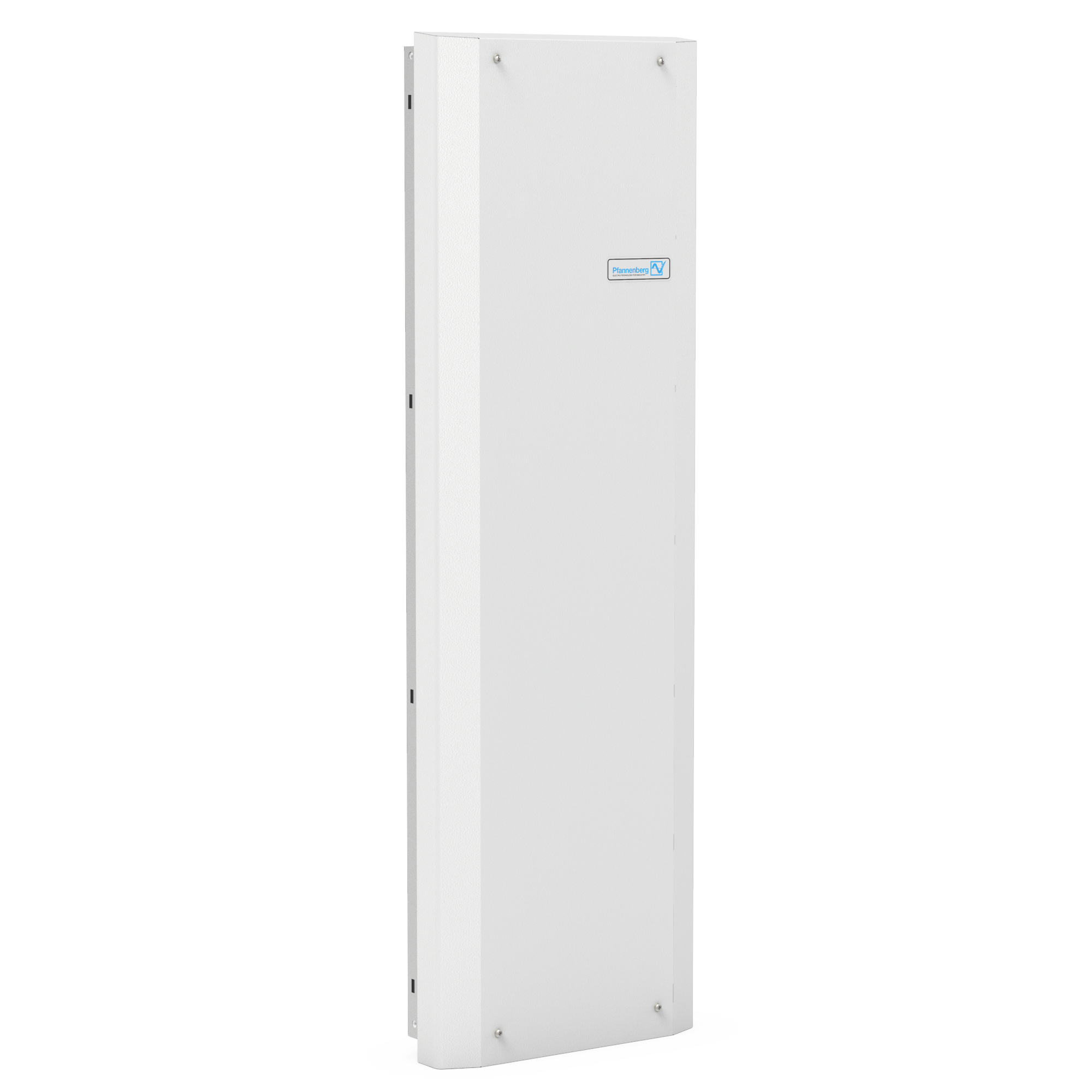
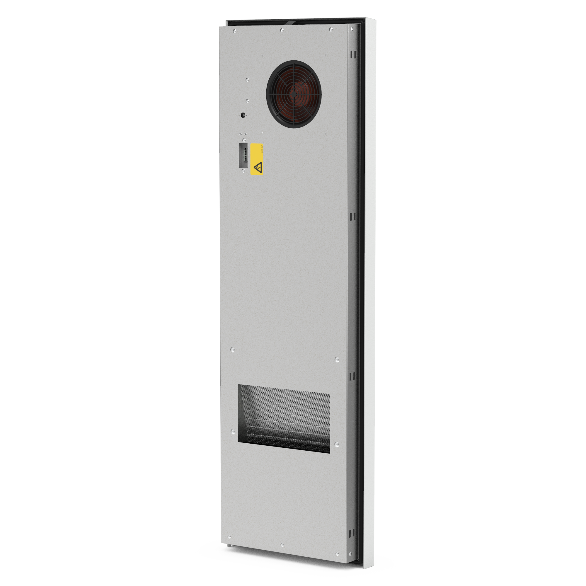
PWI 6302 115V Partially Recessed Air/Water Heat Exchanger
AC 115 V1~,
The use of Pfannenberg air/water heat exchangers is particularly suitable where ambient temperatures are high or the atmosphere proves to be particularly oily or aggressive. Maintenance-free operation and extremely low noise emission. Ideal application areas wherever machines or production processes are cooled by tempered water and water is thus already provided. The advantages of the series at a glance: -system-compatible with chillers -can be integrated in existing cooling circuits -integrated thermostat and solenoid valve for energy-efficient temperature control -high airflow rate and cooling capacity -any power losses that occur are not given off into the room -integrated temperature monitoring with alarm contact -usable under aggressive environmental conditions -independent from the ambient temperature at the place of installation -compact design -seal requires no elaborate reworking of the mounting cut-out -maintenance-free
Technical Data
- Rated voltage V ±10 %
- AC 115 V1~
- Cooling cap. W at l/h
- 5000 W @ 400 l/h
- Power consumption (W10/A35) W
- 91 W
- Current consumption (W10/A35) A
- 0,79 A
- Starting current (W10/A35) A
- 0,97 A
- Type of fuse | Pre fuse
- gG | 2 A
- Type of connection (electro)
- spring-type terminal included with plug
- Type of connection (fluid)
- 13 mm Hose Nozzle, Other Connectors On Request
- Weight (without packaging) kg
- 30,3 kg
- Ambient temperature °C
- +1 °C ... +70 °C
- Control range (adjustable) °C
- +8 °C ... +50 °C
- Water inlet temperature °C
- > +1 °C ... +35 °C
- Permissible operating pressure bar
- max. 10 bar
- Condensate management
- condensate drain
- Protection system according to EN 60529 towards the electrical enclosure
- IP 55
- Design housing
- Galvanised Steel, Electrostatically Powder Coated (200C)
- Design heat exchanger
- copper pipe with aluminium fins
- Colour
- RAL 7035
- Mounting position
- Side Mount
- Dimensions (H | W | D) mm
- 1.549 mm | 485 mm | 142 mm
- Installation depth mm
- 60 mm
- UL-file numbers
- SA33060
- ETIM-Class
- EC002515
- Rated voltage V ±10 %
- AC 115 V1~
- Cooling capacity @ flow rate (W10/A35)
- 17061 BTU @ 400 l/h
- Power consumption (W10/A35)
- 91 W
- Current consumption (W10/A35)
- 0.79 A
- Starting current (W10/A35)
- 0.97 A
- Type of fuse | Pre fuse
- gG | 2 A
- Type of connection (electro)
- spring-type terminal included with plug
- Type of connection (fluid)
- 13 mm Hose Nozzle, Other Connectors On Request
- Weight (without packaging)
- 54 lbs
- Ambient temperature range
- +34 °F ... +158 °F
- Control range (adjustable)
- +46 °F ... +122 °F
- Water inlet temperature
- > +34 °F ... +95 °F
- Permissible operating pressure
- max. 145 psi
- Condensate management
- condensate drain
- Protection system according to EN 60529 towards the electrical enclosure
- IP 55
- Design housing
- Galvanised Steel, Electrostatically Powder Coated (200C)
- Design heat exchanger
- copper pipe with aluminium fins
- Colour
- RAL 7035
- Mounting position
- Side Mount
- Dimensions (H | W | D)
- 61 in. | 19.1 in. | 5.6 in.
- Installation depth
- 2.36 in.
- UL-file numbers
- SA33060
- ETIM-Class
- EC002515
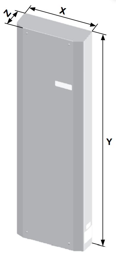
Technical Drawings
- K
- 1510 mm
- L
- 450 mm
- X
- 485 mm
- Y
- 1549 mm
- Z1
- 82 mm
- Z2
- 60 mm
- K
- 59,45 in
- L
- 17,72 in
- X
- 19,09 in
- Y
- 60,98 in
- Z1
- 3,23 in
- Z2
- 2,36 in
PWI variants partially recessed by 60 mm after installation
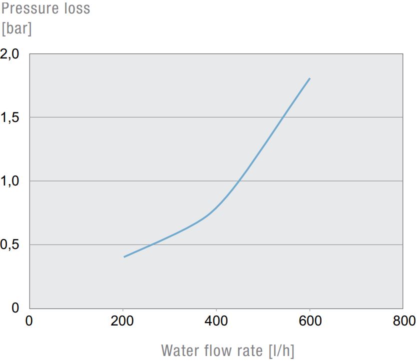
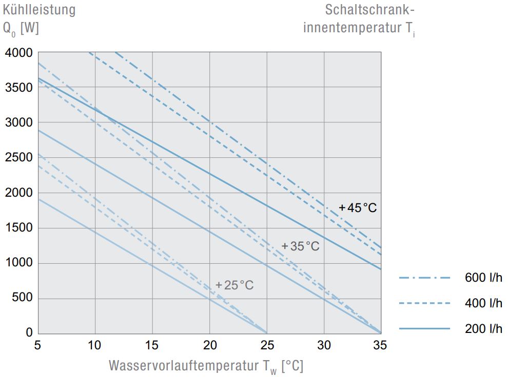
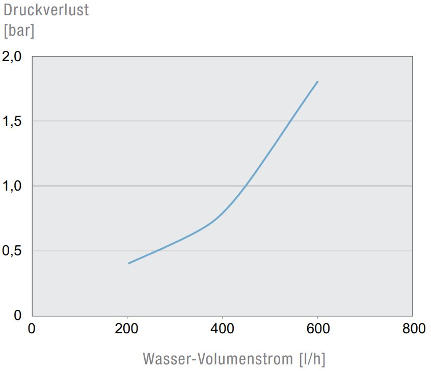
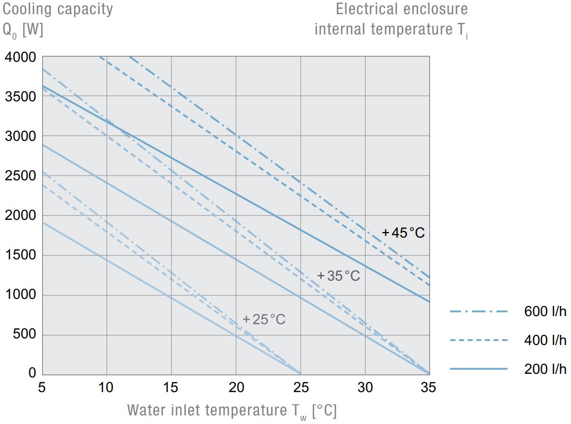
Diagrams
Downloads
| Description | Type | Size | Link |
|---|---|---|---|
| Conformity PWS 7002 - 71002 | 354.45 KB | Download | |
| Conformity PWS 7002 - 71002 | 73.18 KB | Download | |
| Short operat. instruction | 1000.75 KB | Download | |
| Short operat. instruction | 1000.75 KB | Download | |
| Op. inst. PWx 6302 115V 230V | 2.79 MB | Download | |
| CE DECLARATION | 226.05 KB | Download | |
| Op. inst. PWx 6302 115V 230V | 3.61 MB | Download | |
| CE DECLARATION | 231.67 KB | Download |
| Description | Language | Type | Size | Link |
|---|---|---|---|---|
| 3D-model_STEP_PWI6302 | Englisch | ZIP | 1.52 MB | Download |
| Manual_PWx6302_115V_230V | German | 6.34 MB | Download | |
| Cut-out_DXF_PWI_6302_6502 | Englisch | ZIP | 6.79 KB | Download |
| UL_Certificate_PWx_6xxx | German | 378.1 KB | Download | |
| Manual_PWx6302_115V_230V | Englisch | 6.34 MB | Download | |
| Cut-out_DXF_PWI_6302_6502 | German | ZIP | 6.79 KB | Download |
| EAC_Certificate_PW | Englisch | 1.64 MB | Download | |
| Product_Sheet_PWI-PWS_6000T_Connection-Kit | Englisch | 3.9 MB | Download | |
| EAC_Certificate_PW | German | 1.64 MB | Download | |
| Product_Sheet_PWI-PWS_6000T_Connection-Kit | German | 3.9 MB | Download | |
| Product_Sheet_EN_PWI_PWS_6302 | Englisch | 248.85 KB | Download | |
| UL_Certificate_PWx_6xxx | Englisch | 378.1 KB | Download | |
| 3D-model_STEP_PWI6302 | German | ZIP | 1.52 MB | Download |
| Product_Sheet_DE_PWI_PWS_6302 | German | 249.4 KB | Download |

