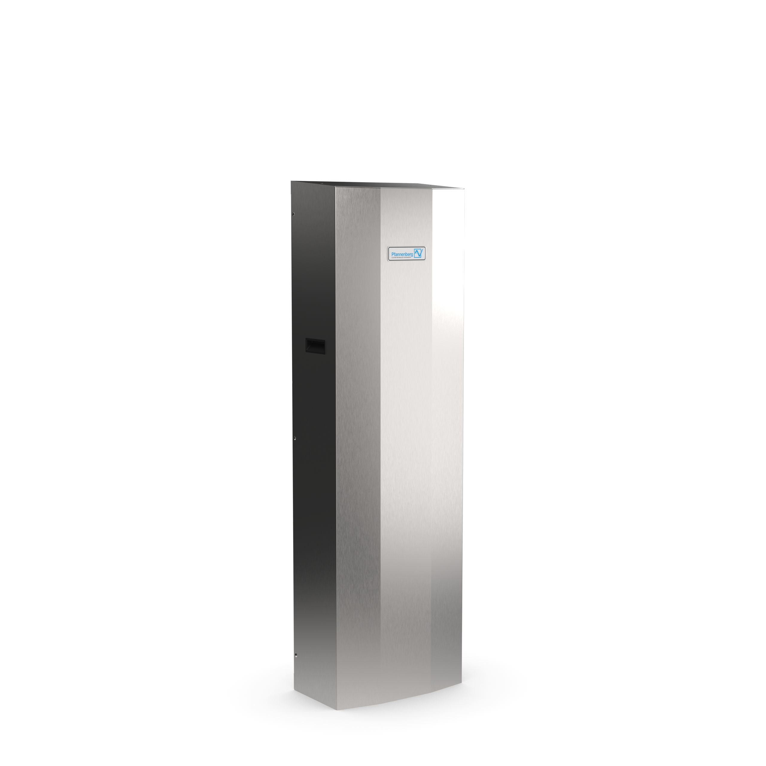
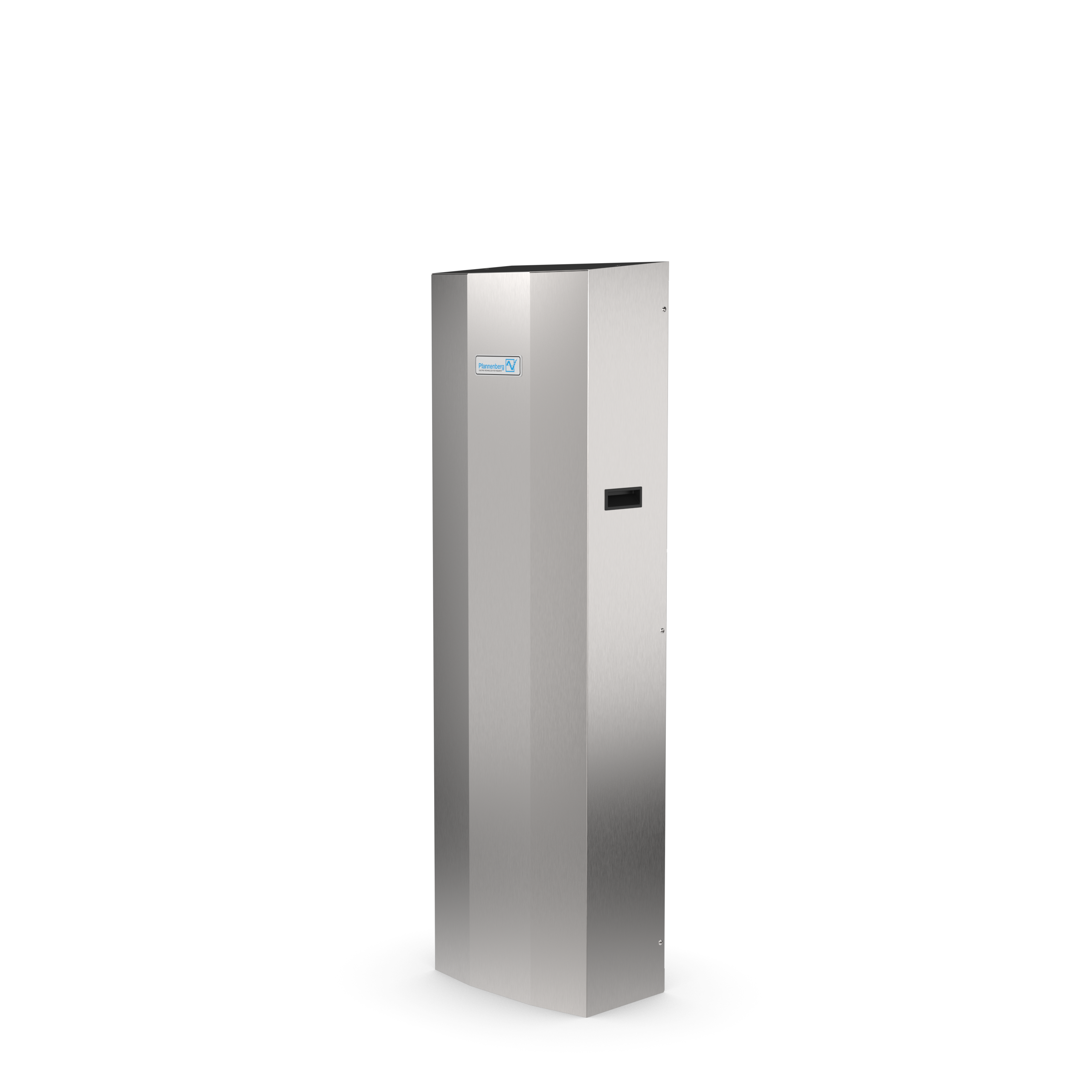
PWS 3202 Air/Water Heat Exchanger
AC 115 V / 115 V1~,
The use of Pfannenberg air/water heat exchangers is particularly suitable where ambient temperatures are high or the atmosphere proves to be particularly oily or aggressive. Maintenance-free operation and extremely low noise emission. Ideal application areas wherever machines or production processes are cooled by tempered water and water is thus already provided. The advantages of the series at a glance: -system-compatible with chillers -can be integrated in existing cooling circuits -integrated thermostat and solenoid valve for energy-efficient temperature control -high airflow rate and cooling capacity -any power losses that occur are not given off into the room -integrated temperature monitoring with alarm contact -usable under aggressive environmental conditions -independent from the ambient temperature at the place of installation -compact design -seal requires no elaborate reworking of the mounting cut-out -maintenance-free
Technical Data
- Rated voltage V ±10 %
- AC 115 V / 115 V1~
- Rated frequency Hz ±1 %
- 50 Hz | 60 Hz
- Cooling cap. W at l/h
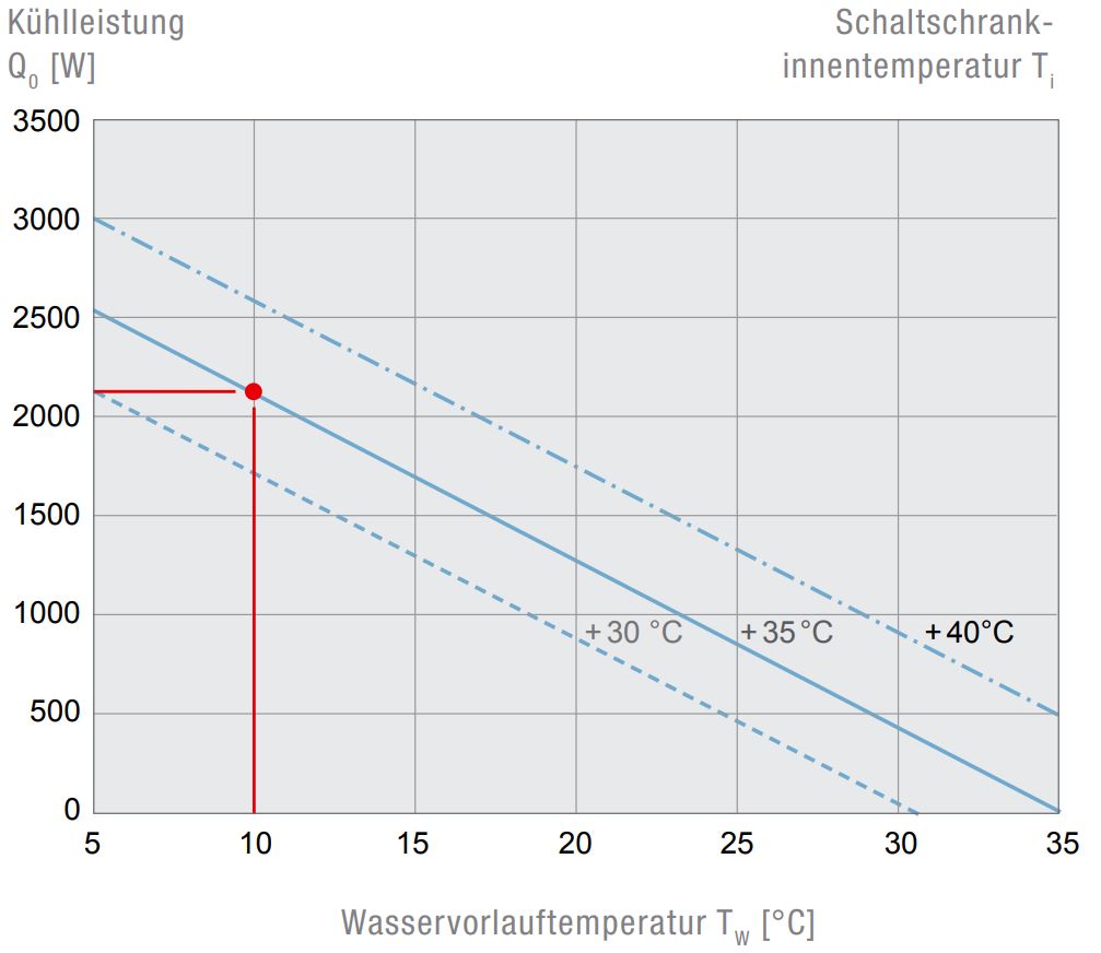
- 2100 W @ 450 l/h
- Current consumption (W10/A35) A
- 0,7 A
- Starting current (W10/A35) A
- 0,83 A
- Type of fuse | Pre fuse
- CC | 1 A
- Type of connection (electro)
- Terminal Block
- Type of connection (fluid)
- 1/2 inch push in fitting
- Weight (without packaging) kg
- 28 kg
- Ambient temperature °C
- +2 °C ... +60 °C
- Control range (adjustable) °C
- +10 °C ... +45 °C
- Water inlet temperature °C
- > +1 °C ... +35 °C
- Permissible operating pressure bar
- max. 10 bar
- Condensate management
- condensate drain
- Protection system according to EN 60529 towards the electrical enclosure
- IP 34
- Protection system according to NEMA towards the electrical enclosure
- 3R/4/4X
- Design housing
- stainless steel 304
- Design cover
- stainless steel 304
- Design heat exchanger
- Copper Tube and Aluminum Fin
- Colour
- 304 SS
- Mounting position
- Side Mount
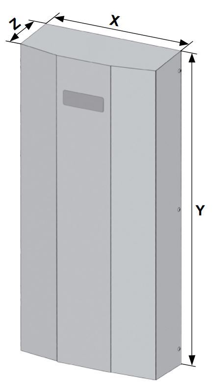
- Dimensions (H | W | D) mm
- 1.318 mm | 400 mm | 229 mm
- ETIM-Class
- EC002515
- Rated voltage V ±10 %
- AC 115 V / 115 V1~
- Rated frequency Hz ±1 %
- 50 Hz | 60 Hz
- Cooling capacity @ flow rate (W10/A35)
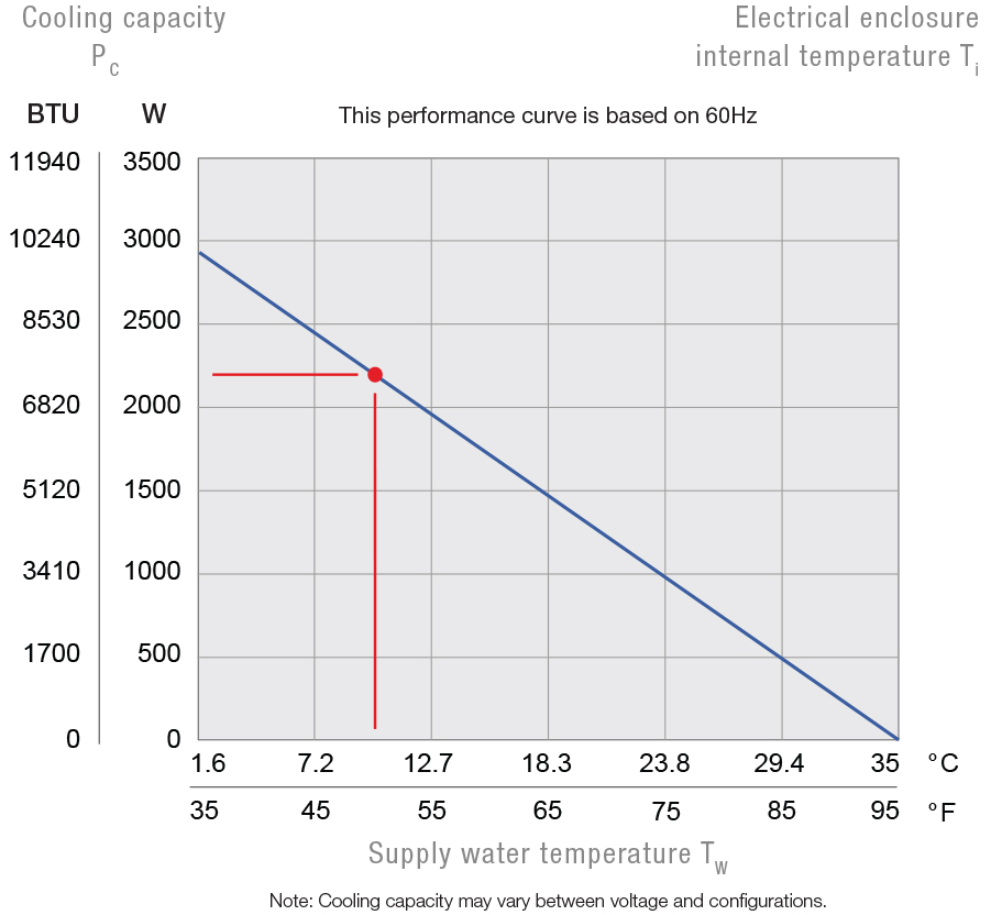
- 7165 BTU @ 450 l/h
- Current consumption (W10/A35)
- 0.7 A
- Starting current (W10/A35)
- 0.83 A
- Type of fuse | Pre fuse
- CC | 1 A
- Type of connection (electro)
- Terminal Block
- Type of connection (fluid)
- 1/2 inch push in fitting
- Weight (without packaging)
- 62 lbs
- Ambient temperature range
- +36 °F ... +140 °F
- Control range (adjustable)
- +50 °F ... +113 °F
- Water inlet temperature
- > +34 °F ... +95 °F
- Permissible operating pressure
- max. 145 psi
- Condensate management
- condensate drain
- Protection system according to EN 60529 towards the electrical enclosure
- IP 34
- Protection system according to NEMA towards the electrical enclosure
- 3R/4/4X
- Design housing
- stainless steel 304
- Design cover
- stainless steel 304
- Design heat exchanger
- Copper Tube and Aluminum Fin
- Colour
- 304 SS
- Mounting position
- Side Mount
- Dimensions (H | W | D)
- 51.89 in. | 15.75 in. | 9.07 in.
- ETIM-Class
- EC002515
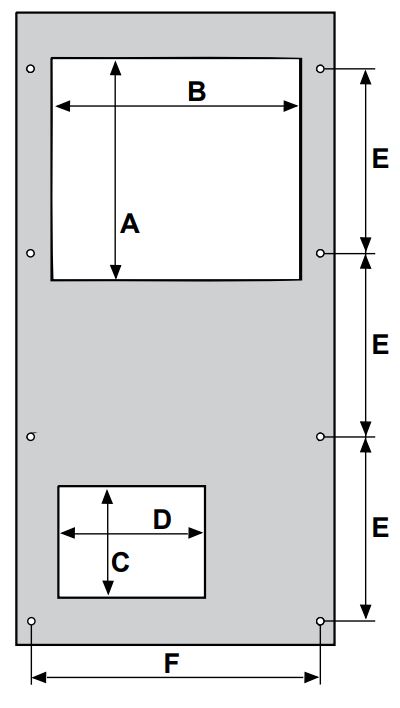
Technical Drawings
- A
- 300 mm
- B
- 310 mm
- C
- 130 mm
- D
- 203,2 mm
- E
- 228,6 mm
- F
- 360 mm
- X
- 401 mm
- Y
- 814 mm
- Z
- 159 mm
- A
- 11,81 in
- B
- 12,2 in
- C
- 5,12 in
- D
- 8 in
- E
- 9 in
- F
- 14,17 in
- X
- 15,79 in
- Y
- 32,05 in
- Z
- 6,26 in
Mounting holes Ø 8 mm
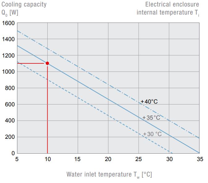
Diagrams
Downloads
| Description | Language | Type | Size | Link |
|---|---|---|---|---|
| EAC_Certificate_PW | Englisch | 1.64 MB | Download | |
| 3D-model_STEP_PWS3202 | Englisch | ZIP | 5.32 MB | Download |
| Product_Sheet_EN_PWS_3202 | Englisch | 216.15 KB | Download | |
| Drawing_PWS_3202 | Englisch | tables.type.file_pdf | 303.05 KB | Download |
| EAC_Certificate_PW | German | 1.64 MB | Download | |
| Drawing_DXF_PWS_3202 | Englisch | DXF | 311.39 KB | Download |
| 3D-model_STEP_PWS3202 | Englisch | STEP | 5.32 MB | Download |
| UL_Certificate_PWS_3xxx_PWS_7xxx | German | 229.67 KB | Download | |
| Product_Sheet_DE_PWS_3202 | German | 215.99 KB | Download | |
| UL_Certificate_PWS_3xxx_PWS_7xxx | Englisch | 229.67 KB | Download | |
| 3D-model_STEP_PWS3202 | Englisch | ZIP | 5.32 MB | Download |
| UL_Certificate_PWS_3xxx_PWS_7xxx | Englisch | 229.67 KB | Download | |
| PWS-Series-Manual-04-22 | Englisch | 5.16 MB | Download | |
| PWS-Series-Manual-04-22 | German | 5.16 MB | Download | |
| 3D-model_STEP_PWS3202 | German | ZIP | 5.32 MB | Download |
| PWS-Series-Manual-04-22 | Englisch | 5.16 MB | Download | |
| EAC_Certificate_PW | Englisch | 1.64 MB | Download | |
| Technical_Data_PWS_3202 | Englisch | 390.79 KB | Download |

